Since its inception in 2006, CompactGTL has focused its entire technology development and commercialisation programme exclusively on the upstream oil & gas sector, recognising problematic stranded gas as the most compelling market opportunity.
The original research, started in the year 2000 as part of the renowned UK Atomic Energy Authority R&D programme at Harwell, established and tested at lab scale the key steps required for a small scale GTL process. Since then CGTL has focussed its development activities on delivering what commercially viable plants need to achieve for the target market. Those key requirements, all of which have been successfully demonstrated, are:-
- High availability – robust and reliable operation to take priority over process efficiency
- Suitable for oilfield conditions – ability to accommodate short and long term fluctuations in feed gas composition and flow rate, as well as fast shutdown and re-start scenarios
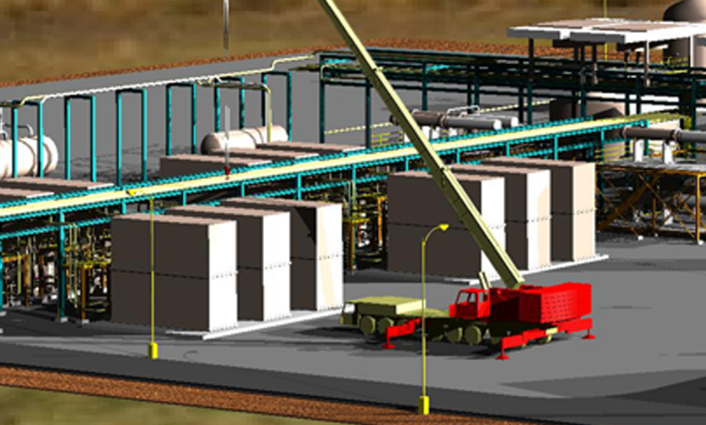
- Deployable in remote locations with poor logistics – proprietary process modules the size of shipping containers individually weighing no more than 30 tonnes
- Maintainability – long service intervals giving low OPEX in remote locations
- ASME VIII code compliant and certifiable equipment – process module manufacturing utilising established, certifiable manufacturing techniques
- Mass produced – utilise established world class companies to form a supply chain to ensure quality and volume delivery for the proprietary items
- Suitable for onshore and offshore deployment and use
- CAPEX and OPEX fall within the ranges required for economic viability
- Oil company demonstration of fully integrated process at meaningful scale
To deliver on these requirements, CGTL qualified and competitively selected world class partners, for reactor design and manufacture, catalyst manufacture, balance of plant engineering and technology development support.
This approach has been coupled with a combined 9 years of actual operating experience on its pilot plant in the UK and the Petrobras demonstration plant in Brazil. As the only company to achieve independent oil company approval of its GTL process (from Petrobras in 2011), CGTL’s technology is today uniquely qualified as “oilfield ready”.
Process Overview
Gas to liquids technology is a process of converting natural gas into longer-chain hydrocarbons, which are liquids at ambient conditions. A GTL plant typically comprises 4 key stages, namely feed gas treatment, synthesis gas generation, an FT section and then an optional product upgrading section.
CGTL’s modular plant design, incorporating multiple reactors in parallel, provides a flexible, operable solution to accommodate oilfield operating conditions.
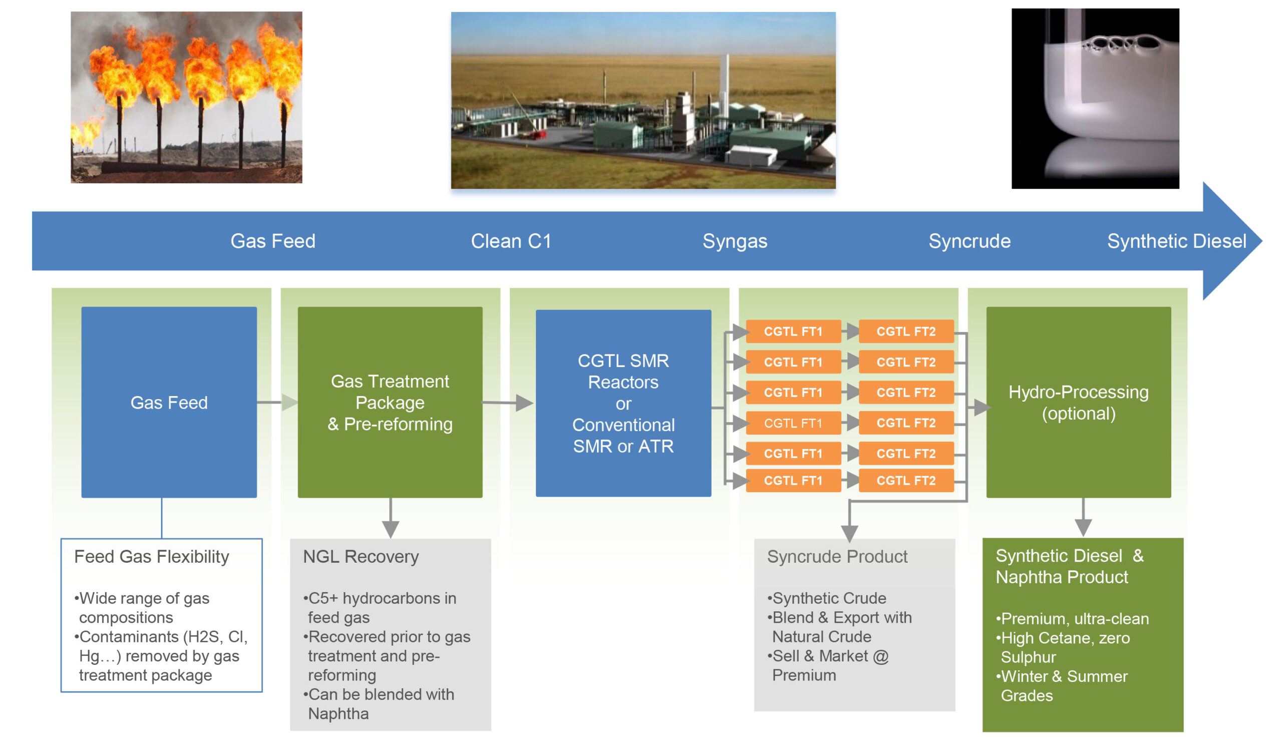
The feed gas, following recovery of any Natural Gas Liquids (NGL’s), first undergoes a sequence of treatment and conditioning steps using commercially available equipment packages. Steam is then added to the clean natural gas stream prior to heating and entry to a catalytic fixed bed pre-reformer (again commercially available equipment) in which the higher hydrocarbons are reacted to give methane, hydrogen and carbon monoxide.
To generate the syngas CGTL’s process utilises either its proprietary, compact modular SMR system, or it can also employ other commercially available synthesis gas generation processes, for example POX or ATR systems, which may be advantageous depending on the project scale and other technical or economic factors.
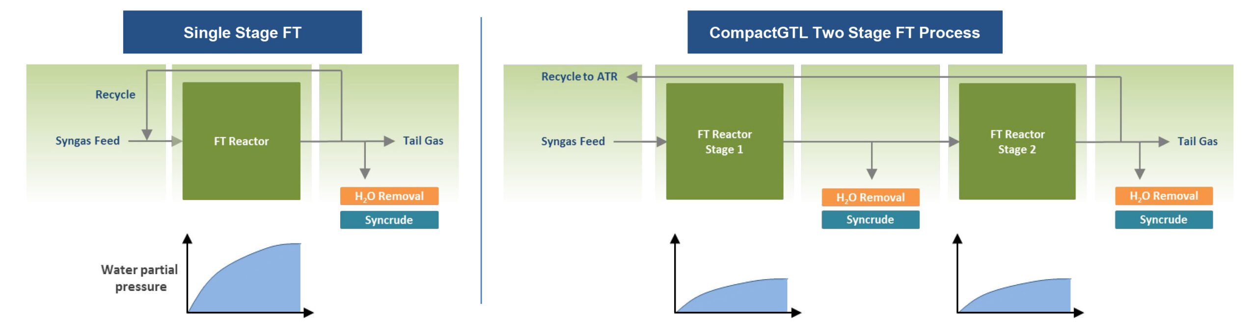
CGTL then employs its proprietary, compact modular FT system which comprises two stages of reaction in series. This patented two-stage system provides longer catalyst life, higher plant availability and reduced OPEX when compared to single stage FT systems.
The FT section produces highly paraffinic, zero sulphur ultra clean synthetic crude oil (sometimes referred to as “syncrude”), a mixture of waxes, middle distillates and naphtha. Depending on locality, the synthetic crude can be blended with the natural crude produced at the oilfield, eliminating the need for additional transportation infrastructure and storage or access to market for the converted product. Alternatively it may be sold as a separate product.
Optionally, the synthetic crude may be converted to diesel blendstock / premium fuel products by integrating mild hydro-processing, readily available from several 3rd party licensors. CGTL therefore has the capability to apply product upgrading to its projects, where the economic drivers dictate, including the ability to produce winter grade diesel blendstocks where appropriate.
Mini Channel Reactors
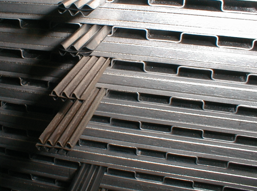
Fundamental to CGTL’s core technology is the adoption of plate-fin heat exchangers to form the structure of both its SMR and FT modular reactors. This allows the precise control of heat and gas flow over the process catalysts, located in a regular array of thousands of closely-spaced channels. These “mini-channels” are so called owing to their dimensions, at about 3-10mm across. CGTL inserts its catalysts directly into plate-fin heat exchanger channels, a process made viable by the simple geometry of the exchanger and the practical cross-sectional dimensions of the channels.
The mini-channel configuration and plate-fin mechanical construction of the reactor units provide two critical characteristics: Firstly, very high specific heat transfer coefficients between the streams. Secondly, high ‘voidage’ or, put another way, relatively low metal inventory, per unit of throughput. The high specific heat transfer coefficients between the streams in the reactor unit enable thermal stability to be achieved for the SMR and FT catalytic reactions, at rates not attainable to date in conventional reactor designs. Together, these two aspects enable the finished reactor modules to meet the size, weight and operational constraints required for remote oilfield deployment, both onshore and offshore.
A further consideration regarding the supply chain for commercial implementation is the availability of an established, scalable and certifiable manufacturing route for plate-fin type reactors. Brazed platefin heat exchangers are extensively used in oil & gas and a wide range of industries as they provide a very good surface area to volume ratio compared to tubular and “plate and frame” units. Critically, ASME VIII pressure vessel code compliance protocols are also very well established for brazed plate-fin units of the type adopted by CGTL. CGTL has adopted Sumitomo Precision Products in Japan as its exclusive reactor supplier, following a long joint development, evaluation and competitive selection process.
Modular Steam Methane Reforming
CGTL’s SMR reactor is in the form of a high temperature alloy brazed plate-fin unit. Every channel contains low pressure-drop catalyst coated metallic foil structures. There are two process streams, in a co-linear flow configuration. The SMR process stream contains a proprietary reforming catalyst which converts the methane and steam into syngas at operating temperatures in the 650-800°C range and at approximately 4 bar. This reaction is endothermic, and the energy is provided by the other stream via a catalytic combustion process. The combustion stream is fuelled by clean fuel gas premixed with combustion air. A further benefit of the CGTL reforming process is the ability to accommodate relatively high amounts of CO2 in the feed gas. Up to 50mol% can be accommodated and the SMR reactor utilises this CO2 in the reforming reaction, actually assisting the production of syngas and ultimately synthetic crude. This avoids the need to remove the CO2 prior to processing, which is normally a requirement for the common forms of gas processing including simple compression for re-injection.
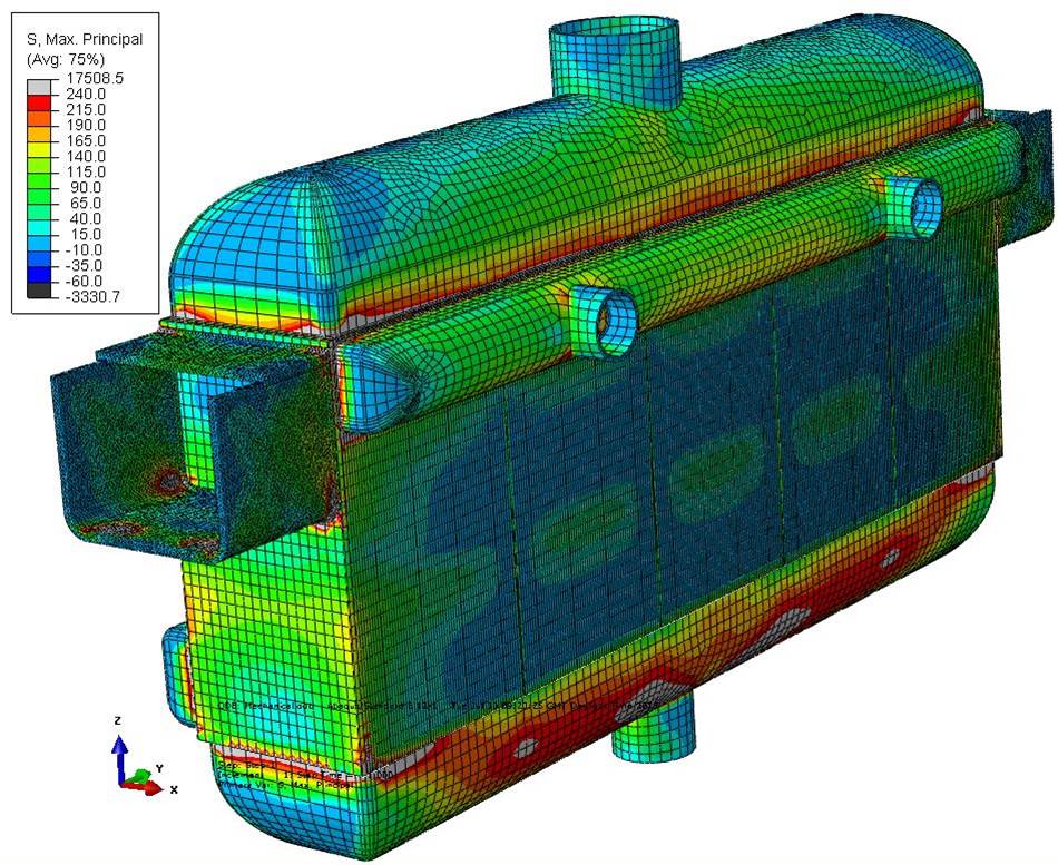
It will be observed that this is a low temperature reforming process, in contrast to more conventional reforming methods operating at over 1,000°C and at higher pressures. This was a deliberate move from an early stage in the SMR reactor development programme, to ensure that the cost-effective brazed plate-fin manufacturing technique could be adopted at commercial scale. The ASME VIII design temperature limit (metal temperature) for brazed structures is 815°C. Furthermore, a key consideration are the thermal stresses induced by the temperature gradients present across the reactor unit during operation. The usable life (design life) of the unit decreases rapidly as thermal stresses rise. CGTL has carefully and extensively developed this aspect throughout the programme, achieving low and uniform thermal stresses induced on a commercial SMR reactor unit during operating conditions.
The removable catalyst inserts used in the SMR reactor allow the catalyst to be coated externally to the exchanger and then inserted. External application of the catalyst on the removable metallic foil based inserts allows a more optimum application of catalyst, whilst allowing removal and replacement at the end of the catalyst life. The application of catalyst on to these substrates is based on a well developed technology used in the mass production of catalytic converters for the automotive industry (developed in the mid-1970s).
For commercial manufacture (and refurbishment) of CGTL’s SMR reactors, an automated system for catalyst insertion and removal was developed and successfully piloted jointly with Sumitomo Precision Products.
CGTL’s modular SMR technology is ideally suited to offshore projects where it is not feasible, from a certification standpoint and other factors, to employ conventional SMR or Auto Thermal Reformer (ATR) systems on floating production facilities.
In each FT stage, the syngas is pre-heated to about 220°C before entering the reactor. The proprietary FT reactor units for the 1st and 2nd stages are identical and comprise arrays of mini-channels constructed using brazed plate-fin construction, with two streams in a co-linear flow configuration. Typical operating conditions for the process stream are 220°C to 235°C at 25 bar. The units are fabricated from stainless steel due to the relatively low FT operating temperature. The FT process channels contain a particulate, Cobalt based FT catalyst. As FT synthesis occurs down the length of each mini-channel, liquid hydrocarbons start to form and migrate under gravity to the outlet header after which they are cooled and collected. The FT reaction is highly exothermic so the co axial adjacent coolant channels carry a pressurised water coolant to maintain acceptable thermal gradients in the radial and axial directions. To date CGTL has achieved over 74,000 hours of operation using its current FT reactor and particulate catalyst combination.

All FT processes create approximately one barrel of waste water for every barrel of synthetic crude product. This means that a partial pressure of water vapour develops in the process channels as the reaction progresses and this can cause hydro-thermal ageing of many FT catalysts. To preserve catalyst life, the CGTL FT process is arranged in two stages, whereby conversion of the syngas to liquid product is limited in the first reactor. The resultant water vapour and condensable hydrocarbon product is then condensed from the tail gas from the first stage before the gas is passed into the 2nd reactor. Further conversion occurs in the 2nd reactor, taking overall conversion to about 90% (including recycle) whilst preserving catalyst life.
The remaining tail gas from the 2nd FT stage can be fed to optional membrane units producing a hydrogen rich stream and a hydrocarbon rich stream (predominantly CH4, CO2, CO). Dependent upon the overall balance of plant and utilities design case, there are different options for tail gas utilisation. In some cases, it is beneficial to recycle some of the hydrocarbon rich stream back to the pre-reformer at the start of the process. Hydrogen rich streams can be mixed with natural gas to provide fuel gas for gas turbine driven power generation or for use in steam boilers.
CGTL’s proprietary 2-stage FT technology is a key factor for the viability of small scale plants in remote locations and is patented in numerous territories. The CGTL 2-stage FT system is capable of providing catalyst life of between 3-5 years (compared to typically 1-2 years for single stage systems). Long catalyst life gives rise to high stability, availability, and low OPEX.
The cooling of CGTL’s FT process is achieved via re-circulating pressurised cooling water flowing through the channels that run in parallel to the process channels where the reaction happens (colinear flow). The combination of liquid water phase cooling fluid and the co-linear flow arrangement provides greater thermal “inertia” and for the temperature increase on the cooling side to compensate for the reduction in syngas conversion reaction rate on the process side. This enables a more uniform overall rate of reaction profile and heat flux at every point in the reactor core. This maintains all the catalyst inventory at a more uniform temperature than would otherwise be possible, further promoting stable performance and long catalyst life. CGTL catalysts are capable of providing a much higher conversion rate, however CGTL choose not operate at the higher rate so as not to compromise reliability, catalyst life and therefore OPEX.
The use of single phase coolant also enables the individual FT reactors on a plant to be operated at different temperature settings, whilst being supplied from a common, cost effective cooling system. Critically, for a complete plant operation, this accommodates operation of reactors with aged catalyst alongside reactors with virgin catalyst following catalyst replacement.
FT Catalyst Replacement
For commercial plants the FT reactor modules will require a periodic removal and refurbishment cycle to replace aged catalyst with fresh catalyst in order to maintain the system performance. In CGTLs plants FT catalyst replacement would be expected to occur every 3-5 years. Reactor modules will be isolated in groups for removal and replacement with refurbished reactors containing fresh catalyst, whilst the remainder of the plant remains operational, maximising plant availability. The duration of this change-out is expected to be of the order of 4-5 days per group. These change-out activities can be phased in campaigns such that the plant exhibits broadly the same overall output capacity at any given time, and the workload for reactor replacement and refurbishment activity is spread out evenly.
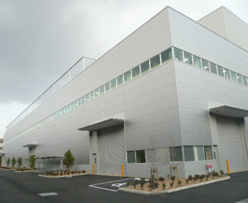
The reactor refurbishment activity, to replace the FT catalyst, will take place outside of the main plant area, (“ex-situ”) allowing the GTL plant to remain fully operational. Refurbishment will take place in a factory environment within a dedicated purpose built facility. This approach enables the appropriate catalyst removal, handling, re-loading and conditioning systems and associated quality control procedures to be reliably implemented in a safe and controlled environment, away from the operational plant. The refurbishment facility can either be provided at the site itself, separate from the GTL plant, or, in a centralised facility offsite. The favoured approach will depend on specific project location factors.
The design and layout philosophy of the FT section of the GTL plant is such that the reactor groups can be isolated and work can take place safely replacing a group whilst the rest of the facility remains in operation.
The CGTL ex-situ catalyst replacement philosophy is a vital component in the company’s capability to provide safe, reliable, high up-time plant operations in what will be challenging remote locations.
Scale-out to Commercial Plant
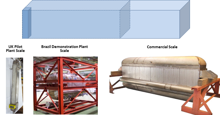
CGTL will adopt the same scale-out approach it used when constructing the Brazil plant based on experience of the pilot scale reactors used in the UK. With its partner Sumitomo Precision Products, CGTL will simply increase the number of reactors channels (layers) per reactor unit. A full size FT reactor, as shown below, is just a multiple of the demonstration scale reactor units used in Brazil. In turn, it is worth noting that the demonstration reactors successfully built and operated for the Brazil plant were scaled out versions of those tested at the UK pilot plant.
All other aspects of scaling to a commercial plant are well understood based on known engineering principles and practice, such as flow distribution modelling using Computational Fluid Dynamics (“CFD”), pipe stress analysis for modularisation of reactor units etc. As described in the following section, the remaining equipment items and systems required for a complete commercial plant are all widely adopted and field demonstrated at scale across the industry. In conjunction with the expertise and experience provided by CGTL’s engineering partner, Fluor, CGTL is engaging only leading worldclass 3rd party licensors for the major balance of plant process equipment.